Balancing two anchor points
In Rescue, it is common to create a centralized anchor while sharing two anchor points. There are many reasons why we would use two or more anchor points; sometimes this is because the anchors are not exactly where we need them to be and other times it could be because the anchors are perceived as “marginal”. Although it is ill-advised to use marginal or questionable anchors unless they are backed up sufficiently, the following information should help you in pre-determining how much stress you are actually applying to the anchors during a rescue evolution before they are loaded.
Many rescue instructors, firms, and institutions may refer to angles as “Ideal”, “Yes”, “Cautionary” and/or “Terrible” angles and this quick overview may help further explain and/or challenge your understanding of these meanings.
DOWNLOAD PDF (Click on Diagram)
The IPS Group – Vector Angles – Anchors for Rigging
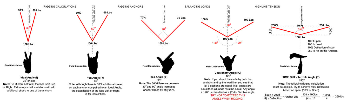
30˚ “Ideal” Angle: An “Ideal” angle is an angle that is between 0˚ and 30˚. What makes the angle considered to be “Ideal” is that the weight of the load is split evenly between both anchors. For example, a 30˚ load holds approximately 50% of the weight. In the diagram, you can see how a 100lb load only has 50lbs on each anchor which is 50% of the 100lbs. If there was an “S” type load cell* on each of the anchors connected to the rigging, you could see the results as you modified the angles. A challenge to the idea of the angle being “Ideal” is that if there is a slight shift of the load, the anchor opposite of the load shift will receive a very rapid and massive amount of load gain. If the anchor is marginal, it could result in anchor failure. The easiest way to identify if the anchor angle is approximately 30˚ is by making a peace sign with your hand. The angle between your index (pointer) finger and your middle finger is roughly 30˚.
“Yes,” angles are typically between 30˚ and 90˚. The considerations for “yes” angles are that there are very insignificant increases in weight to the anchors but with quite a large range of angle increase. Overall, as you can see on the diagram, there is an increase of weight between the 30˚ and 90˚ angles of only 20% to each anchor. This angle range of 50˚ having a 20% increase to each anchor is the primary reason for the classification of “Yes” angles. These angles are easily identified due to the load line and anchor lines looking like the letter “Y”. A shift in the load also must be much more dramatic before additional anchor stress is achieved.
60˚ “Yes” Angle: By increasing the 30˚ angle to a 60˚ angle between the anchors creates a 10% increase in anchor stress. As seen in the diagram, the doubled angle only shows the additional 10lbs per anchor to hold a 100lb weight. The 60lbs of anchor stress per anchor to hold the 100lbs is far more stable than the ideal angle if the load were to shift to the left or the right. Whenever possible, try and achieve a 60˚ angle for balancing loads. A quick field calculation for assessing a 60˚ angle is by holding up the “Hook ‘em Horns” hand signal. This is achieved by holding up your index (pointing) finger and your pinky finger while tucking the two middle fingers with your thumb. This natural span and the angle is very close to a 60˚ angle.
90˚ “Yes” Angle: This angle achieves a right angle which is very easy to identify and verify in the field. You could use a book, or a phone or almost anything lying around that has a right angle in order to visually see this angle. Also, if you make the letter “L” using your index (pointing) finger and your thumb you can also see this angle. A 90˚ angle only places 70% of the load on each anchor. As seen in the diagram, a 100lb load only has 70lbs on each anchor.
120˚ “Cautionary” Angle: The “Shaka” or “Hang Loose” hand signal is a rough estimation used in the field for a 120˚ angle. The reason for this “cautionary” angle is due to the forces applied to the anchors. At this angle, the full weight of the load is being applied to both anchors evenly. In the diagram, it shows a 100lb weight and both anchors holding the 100lbs. the reason for this is a simple formula. If you dissect the circle by both of the anchors and the load line, you will see that all three sections are equal. If all angles are equal, then all loads must be equal. The symmetrical tension on the anchors and load line should indicate that each of the anchors should be able to hold the load by themselves. Never use “marginal” anchors when rigging in this vector angle range. A slight change in angle will cause a dramatic increase of stress put on the anchors. Any angle that is greater than 120˚ is classified as a “Terrible” angle. Without a clear understanding of physics, never try and rig outside of 120˚ angle.
150˚ “Terrible” Angle: Although most would classify a 150˚ angle as terrible, my thoughts are a little different. Under normal circumstances, I would not try and rig an angle this wide due to the excessive stress placed on the anchors, but in certain applications, they are very useful. Typically, when applying these wide angles their uses are not only wanted but may be very necessary. This is usually the case when building Highline systems, Tyrolean systems or Offsets. My typical name for the angles is not “Terrible” but more like “Time Out”. The main reason is I believe you should take the time when building these style systems and do the math! Physics play a huge role in the failure of these systems in every part. These wide angles must be calculated and all equipment associated with these systems is an integral part of the entire degradation of the system, but most certainly the anchors. Very flat trajectories yield very high stressors for the anchors in these systems. I am not saying you could not build a system that had a 2.5% deflection, but if you do, understand the limitations of the entire system.
Deflection is key when rigging anything beyond 120˚. First, let’s assume some basic guidelines. We would be using ½ kernmantle static ropes as well as all “G” rated equipment. The load would not exceed the NFPA two-person load of 600lbs. As all of this equipment would be rated for the coveted 15:1 safety factor (9,000lbs), in all actuality, we would be attempting to hit a 10:1 safety margin. A 10:1 safety factor in our systems is more like a “Holy Grail”, but with proper rigging and calculations, it could be achieved.
Here is the formula:

The IPS Group – Anchor Stress Formula
Real World Application:
Estimate the load and multiply it by the distance between the two anchors. Let’s say we have a load of 400lbs. and a distance between the anchors of 100ft. we would multiply the load of 400lbs times the distance of 100ft totaling 40,000lbs. Now you can see that the “G” rated equipment would fail since its ratings are around the 9,000lb mark. At this point, you should be looking at “Sag” more than anything else in order to reduce that tension. Here is the simple way to calculate “Sag” or deflection. If we are using a single ½ inch kernmantle rope, we would want no less than 10% deflection. A 10% deflection of the entire distance between both anchors, which is 100ft distance, would be a 10ft deflection. Multiply 4 times 10, and you get 40. Now, 40,000 divided by 40 equals 1,000lbs. This shows that a 400lb load with a distance between anchors of 100ft and a deflection of 10ft (10% of the distance) would generate a 1,000lb hit on the anchors. As seen in the diagram, we are using the same formula but a weight of 100lbs, a span of 10ft, and a deflection of 1ft. If these numbers are plugged into the formula, you can see that there are 250lbs of force on each anchor. When using this formula, you are attempting to achieve a 150˚ angle, regardless of the scale between anchors. If less deflection is required, additional rigging must be applied to keep a 10:1 safety factor.
For further information about this or other related topics please contact Shayne Torrans, HSEQT Manager – The IPS Group.
*S Type Load Cell: are low-cost and high-performance side mounted load cells suitable for a number of weighing and general force measurement applications. http://www.cmcrescue.com